|
Bank Angle and the Physics of Standard Rate Turns (continued)
II - Forces Acting on Aircraft (constant altitude)
We're going to begin by looking at the physics and geometry of a standard rate turn starting with the straight and level flight before the turn.
Straight and Level Flight Before the Turn
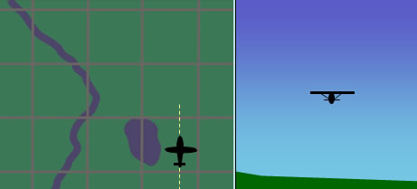
Fig 2-1 Aircraft flying straight and level
Figure 2-1 shows our hypothetical aircraft flying straight and level. The left image is the top map view, and the image on the right represents the aircraft as seen from behind.
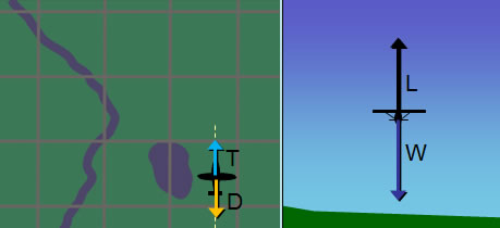
Fig 2-2 Aircraft flying straight and level (thrust, drag, lift and weight forces)
Figure 2-2 on the left shows the thrust (T) and drag (D) forces. Since the aircraft's true air speed (TAS) will remain constant during straight and level flight and then subsequently during the execution of the standard rate turn in our hypothetical example, we are not going to concern ourselves with these forces. Also note that thrust (T) and drag (D) will cancel each other out both before and during the turn, but they will not remain the same. During the turn, drag (D) will increase due to the need to generate more lift; as a result more thrust (T), added by the pilot, will be necessary to compensate for this increase in drag. This thrust increase is necessary if airspeed is to remain constant. We will examine why lift has to increase in more detail shortly.
Figure 2-2 on the right shows the lift (L) and the opposing weight (W) force during straight and level flight. During this flight condition these forces cancel each other out. That is why the aircraft will remain at its altitude and flight path (provided it is not already climbing or descending) and will not accelerate vertically (begin to ascend or descend).
During Standard Rate Turn
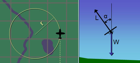
Fig 2-3 Aircraft banking (lift and weight forces)
Figure 2-3 on the right shows the lift (L) and weight (W) forces when the aircraft banks at an angle  and begins the circular turn. Although not obvious in figure 2-3, as the aircraft's bank angle increases, the lift (L) force has to increase if the aircraft is to remain at the same altitude. This is because the part of the lift acting vertically has to remain the same to counteract weight. As the aircraft banks and lift force is tilted, less of it is acting vertically so the only way to compensate for that is to increase lift (L). and begins the circular turn. Although not obvious in figure 2-3, as the aircraft's bank angle increases, the lift (L) force has to increase if the aircraft is to remain at the same altitude. This is because the part of the lift acting vertically has to remain the same to counteract weight. As the aircraft banks and lift force is tilted, less of it is acting vertically so the only way to compensate for that is to increase lift (L).
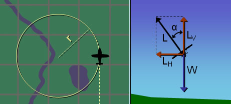
Fig 2-4 Aircraft banking (lift components and weight forces)
In figure 2-4, the lift force (L), which we can refer to as total lift, is shown broken down to its horizontal (LH) and vertical (LV) components. These are not additional forces, they are simply another way to represent the total lift force (L) . The total lift force (L) can also be thought as a resultant force of those horizontal (LH) and vertical (LV) lift forces.
Now we can see more clearly how the vertical lift (LV) counteracts the weight (W). When the aircraft banked, the lift force increased such that it's vertical component (LV) remained equal and opposite to the weight (W) force. Otherwise the aircraft's altitude would change. Therefore the vertical component of lift (LV) and weight force (W) will cancel each other out during the bank, leaving the horizontal component of lift (LH) as the remaining force. This horizontal component of lift (LH) force is what will make the aircraft turn in a circular flight path.
IMPORTANT: We are assuming the turn is coordinated (ball centered). There should be no slip or skid.
|

