Surf with confidence!
  Site has been tested by:
    Norton™ Safe Web
    McAfee SiteAdvisor ®

   Miscellaneous   More functions than your average e6b:
Calculators use multiple units for users of all countries
 

Introduction


Essential Calculators for Flight Maneuvering, Performance, and VOR Navigation.


This page gathers a vital collection of calculators for in-flight maneuvering, performance analysis, and radio navigation. While these specialized tools don't fit into a single category, they solve critical problems for maintaining precise aircraft control and situational awareness. Our "Miscellaneous" toolkit includes:
  • Climb & Descent Gradient
  • Gliding Distance & Glide Ratio
  • Rate of Turn + Bank Angle and Load Factor
  • Pivotal Altitude
  • Off-Course Problems
  • Time to VOR
  • Distance from VOR
These tools complete our comprehensive flight planning suite, joining our dedicated calculators for Altimetry, Weight & Balance, and core Navigation.

Each calculator is built with a powerful "inverse" feature: simply leave any single field blank, and the tool will solve for it. This makes it perfect for "what-if" scenarios, designing training problems, or planning a flight with partial information. Full support for multiple units is included for maximum flexibility.
 

Page Table of Contents

Use these links to go directly to desired calculator
  Climb & Descent Gradient Off-Course Problems
  Gliding Distance & Glide Ratio Time to VOR
  Rate of Turn, Bank Angle and Load Factor Distance from VOR
  Pivotal Altitude    

Climb & Descent
Gradient


Diagram showing descent angle is the angle in a right triangle formed by distance descended on opposite side and distance traveled on the adjacent side.Equation showing that climb, or descent gradient, equals distance climbed, or descended, respectively, divided by the distance traveled.

Ground Speed     [knots]   [km/h]   [sm/h]
Rate of Climb or Descent     [ft/min]   [m/min]   [m/sec]
Climb or Descent Gradient    [ft/Nm]
   [ft/sm]
  [m/km]
 [m/sm]
  [ft/km]
 [m/Nm]
      
Inverse of:          
Climb or Descent Gradient
   [Nm/1000 ft]
   [sm/1000 ft]
 [km/1000 m]
 [sm/1000 m]
 [km/1000 ft]
 [Nm/1000 m]
Climb or Descent Angle    [ o     
Grade Ratio (to 1)   : 1     
Inverse Grade Ratio* (to 1)
  : 1  *Note: same as glide ratio if descending
Climb or Descent Grade    [%]     

      Enter any two fields then press "Eval" on any remaining field for that field's result.  

Gliding Distance &
Glide Ratio


Diagram showing glide angle is the angle in a right triangle formed by vertical distance descended on opposite side, and horizontal distance traveled on the adjacent side.Equation showing that glide ratio, equals vertical distance descended, divided by the horizontal distance traveled.

Horizontal Distance Traveled     [Nm]   [km]   [sm]
    [ft]   [m]  
Vertical Distance
(Height) Descended
    [ft]   [m]   [Nm]
Horizontal Distance Traveled per Vertical Distance (Height) Descended    [Nm/1000 ft]
   [sm/1000 ft]
 [km/1000 m]
 [sm/1000 m]
 [km/1000 ft]
 [Nm/1000 m]
      
Vertical Distance (Height) Descended per Horizontal Distance Traveled    [ft/Nm]
   [ft/sm]
  [m/km]
 [m/sm]
  [ft/km]
 [m/Nm]
Glide Angle    [ o     
Grade Ratio (to 1)   : 1     
Glide Ratio (to 1)
  : 1  *Note: same as the inverse of Grade Ratio
Glide Grade    [%]     

      Enter any two fields then press "Eval" on any remaining field for that field's result.  


Rate of Turn
Bank Angle
Load Factor

                                                        
Diagram showing a top view of an aircraft flying in a circle with the turn radius. A view behid the aircraft showing an aircraft at a bank and total lift, as well as the vertical and horizontal components of lift.
 Main Variables
Ground Speed     [knots]   [km/h]   [sm/h]       
Time for 360o Turn     [min]   [sec]         
Bank Angle    [ o            
Load Factor* (L/W)
  *Note: this is also the amount of "g" forces
  experienced by the aircraft's occupants

 Correlated Variables
Radius of Turn       [Nm]   [km]   [sm]  
Vertical Lift to Weight Ratio (LV/W)          
Horizontal Lift to Weight Ratio (LH/W)          

      Enter any two fields (on the Main Variables)  then press "Eval" on any remaining field for that field's result. Note that
      Bank Angle and Load Factor both count as one field. Correlated variables will be calculated once the "Eval" button is
      pressed.

Pivotal Altitude

                                           
Diagram showing aircraft flying around a reference point at pivotal altitude.
Ground Speed     [knots]   [km/h]   [sm/h]  
Pivotal Altitude     [ft]   [m]    

      Enter any field and instantly get the other field's result.

Off-Course
Problems

                                                                                                    
Diagram showing the relationships between distance flown, distance off-course, course change to parallel, distance to destination, distance off-course, course change to converge, and total course change to intercept.  Main Variables Part I
Distance Flown     [Nm]   [km]   [sm]   [ft]
Distance Off-Course    [Nm]   [km]   [sm]   [ft]
Course Change to Parallel    [o      


 Main Variables Part II

         
Distance to Destination    [Nm]   [km]   [sm]   [ft]
Distance Off-Course    [Nm]   [km]   [sm]   [ft]
Course Change to Conv.    [o      

 Correlated Variables
Total Course
Change to Intercept
    [o  

      Enter any two fields (on the Main Variables Part I)  then press "Eval" on any remaining field for that field's result. Next
      enter any two fields (on the Main Variables Part II)  then press "Eval" on any remaining field for that field's result. The
      "Total Course Change to Intercept" will be calculated as "Course Change to Parallel" + "Course Change to Conv."
 

Time tp
VOR

                                                    
Diagram showing the two steps to determine time to VOR. Step 1 fly straight and perpendicular to your initial bearing. Step 2 note how many degrees has the bearing changed. The time to the VOR is the time it would take, if you immediately fly towards the VOR after step 2.
Time Flown (1-2)   s [hrs] [mins] [secs]
Bearing Change    [o      
Time to VOR   s [hrs] [mins] [secs]

      Enter any two fields then press "Eval" on any remaining field for that field's result.

Distance from
VOR

                                                      
Time to VOR   s [hrs] [mins] [secs]
Ground Speed    [knots]   [km/h]   [sm/h]  
Distance to VOR    [Nm]   [km]   [sm]   [ft]

      Enter any two fields then press "Eval" on any remaining field for that field's result. Note: to obtain "Time to VOR" use
      the function above.


  Navigation Simulator  
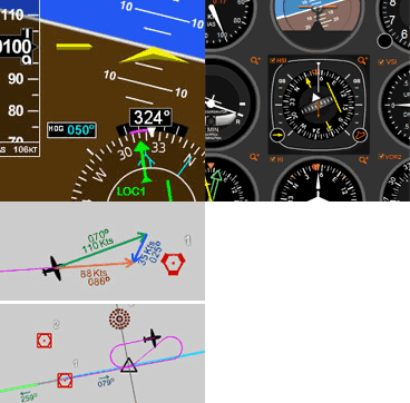
  Practice in our simulator specifically designed for learning the basics of instrument navigation. Try the Navigation Simulator, available for Windows PC. Now completely free, forever!. There is also an online version that runs directly on this website, and can be viewed on a Windows PC, Mac, or Linux OS.  


  Free Online Simulators
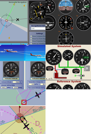
No installation required. These simulators are ready to run on your web browser and have a rich set of features. Practice basic VOR, ADF, RMI and HSI intrument orientation and execute holding patterns. Other simulators include pitot static system and altimeter errors. Click here to go to main online simulator page.


Units and Abbreviations

Length or Distance

m -  meters
ft -  feet
Nm -  nautical miles
km -  kilometers
sm -  statute miles
 

Speed

knots -  knots (Nm/h)
km/h -  kilometers per hour
sm/h -  statute miles per hour
 

Time

h or hr(s) -  hour(s)
m or min(s) -  minute(s)
s or sec(s) -  second(s)
 

Angle

o degrees


By Luiz Roberto Monteiro de Oliveira. Screenshots and video captures allowed (personal, business or military)
as long as credited to author and link to this site or URL included. Permission required for all other uses.