Instructions for Use
Choose your instruments from the "Panel Setting" drop-down menu. Drag aircraft on map to change the aircraft's position in relation to the facility. If North Up is selected aircraft heading changes can be set by positioning the cursor close to the aircraft on the map then clicking the button when a "-" or "+" appears. If Heading Up is selected, aircraft heading changes can be set by positioning the cursor close to the navigational facility on the map then clicking the button when a "-" or "+" appears.
Additionally there are two ways to set the aircraft's heading:
1. Double clicking on the aircraft will cause a small window near the aircraft to open with the current heading in the edit box. Changing the value in the edit box to any value from 1 to 360 will change the aircraft heading to that heading.
2. Holding Shift key down and moving the cursor near the aircraft center will display a blue arrow extending from the center of the aircraft with the current direction of the arrow from the aircraft in degrees displayed on the line. While holding the Shift key down and moving the mouse cursor around the map, the arrow radiating from the aircraft will follow the mouse constantly showing the direction from the aircraft. Clicking the mouse button will change the aircraft heading to the current direction of the blue line. Release the Shift button to hide the blue line.
Knobs are set the same way as the heading of the aircraft (as described above), except that instead of placing the mouse on the aircraft symbol, the mouse is placed on the knob.
You can use the keyboard to control the movement of the aircraft. The following are the keys that control the aircraft:
 FIGURE 1 Keyboard commands
| IMPORTANT KEYBOARD CONTROL NOTE: The simulator start button must be pressed and the aircraft rotating-around-the-globe icon (Fig. 2) must be moving for the keyboard commands to work. In addition, if clicking outside the simulator (like clicking on the browser scroll bar, text or any other area outside) the browser may stop sending the keyboard commands to the simulator. You must click on any blank portion of the simulator to allow the browser to transfer keyboard commands to it. You can also still drag and reposition the aircraft even if it is moving.
When Heading Up is selected, even though it may seem that the aircraft rotates around the navigational facility, the aircraft remains in the same position when changing heading. The reason for this is that the display will always show the navigational facility in the center of the display. This means that regardless if North Up or Heading Up is selected the aircrafts position will always be relative to the navigational facility. |
|
Reference
FIGURE 2 Main Simulator Parts
Main Simulator Parts:
Horizontal Panel / Map
Displays the horizontal position of the aircraft in relation to the navigational facility the same
way an IFR en route chart or an approach plate's plan view would.
Aircraft Movement Control Display
Area where indicated airspeed, and bank angle. These are directly controlled by the keyboard commands.
Aircraft Miscellaneous Instruments
Location for other instruments such as DME, flight time, and chronometer.
Aircraft Motion - Start / Pause Control
The start / pause button controls when movement begins or pauses. Flight time and chronometer stop when aircraft motion stops. Aircraft circulating icon reinforces if aircraft is moving and what rate is the simulation speed. This control can also be activated through the keyboard shortcut ”P”.
Instrument Panel
Area where the analog instruments, such as HSI, VOR, RMI, heading indicator, and ADF are located. The panel can be chosen under the panel setting drop-down menu
Panel Setting Drop-down
Use to select the types of instruments displayed in the instrument panel
FIGURE 3 Horizontal Navigation Map
Horizontal Navigation Map
Navigational Aid Symbol
Represents the Navigational Aid selected and is similar to the representation found on aeronautical charts.
From Region
Shows on the Horizontal Navigation panel the region where the VOR / HSI flag will display From if the aircraft is positioned in the From region regardless of heading.
To Region
Shows on the Horizontal Navigation panel the region where the VOR / HSI flag will display To if the aircraft is positioned in the To region regardless of heading.
Wind Triangle Aircraft Radial Line Compass Rose |
|
Magnetic North Symbol
Similar to the compass rose in that it is used to indicate the direction of the magnetic North. In this case it is the symbol on the NDB (navaid 3).
Course (CRS) Setting From / To Line
Shows a line passing through the navaid in the direction of the course that is set in the instrument and another line that is reciprocal to that course.
Aircraft Bearing From Symbol
Line passing through the NDB (navaid 3) and the aircraft showing the bearing that the aircraft is in relation to that navaid.
Map Scale
Displays the width of the horizontal panel map in nautical miles.
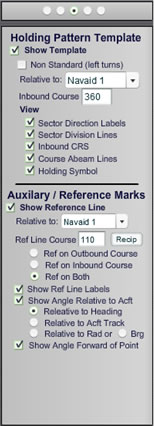
FIGURE 5 Holding Pattern Template
Holding Pattern Template
The holding pattern template is available to assist entry and execution of the holding patterns. Labels with inbound course and sectors are also displayed in this template.
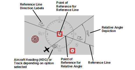
FIGURE 3 Auxiliary / Reference Marks
Auxiliary / Reference Marks
The ability to display on the map intercept angle, angle in relation to course, and angle in relation to radial has been added. This can be found under Other Settings, Auxiliary/Reference Marks.
Options Panel One
Wind Triangle Show Arrow: if show triangle is selected, this option will place arrows on the wind triangle vectors. Wind Dir: sets the value for the direction from where the wind is coming. Trace Path Show Trace: if the path of the aircraft was recorded or is being recorded through the “Trace On” option, a line will be drawn through the points that the aircraft traveled on the map. Map Zoom Auto Zoom In: selects if zooming in is automatic when the aircraft is moving Aircraft Motion Settings Max Bank: this selects the maximum banking limit when using the keyboard commands to bank. The default “Std Rate” automatically limits the bank to standard rate based on the aircraft’s current speed. Global View Note that when “North Up” is NOT SELECTED additional computer processor performance will be necessary to keep moving the map as the aircraft heading changes. This can reduce the simulator’s performance. If you see that the simulator’s performance is slow it is best to keep the “North Up” option selected. Show Map: when deselected, hides all of the features on the map. Use this mode to navigate on instruments alone and test your navigation skills. Show Aircraft: when deselected, hides the aircraft icon on the map, along with aircraft specific map features. |
|
|||||
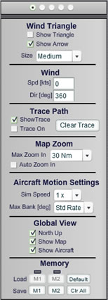
Memory
Load: retrieves all the settings and aircraft position from a memory slot.
Save: stores all the settings and aircraft position in a temporary memory slot.
Default: restores all default settings and default aircraft position.
Clr All: clears all the temporary memory slots.
Options Panel Two Navaid 1 Map Options Show Aircraft Radial: selects whether a line drawn from the navaid through the aircraft, showing the aircraft’s radial in relation to that navaid, is displayed. Navaid 2 Map Options Show Aircraft Radial: selects whether a line drawn from the navaid through the aircraft, showing the aircraft’s radial in relation to that navaid, is displayed. Navaid 3 Map Options Show Aircraft Bearing: selects whether a line drawn from the navaid through the aircraft, showing the aircraft’s bearing to that navaid, is displayed. Show Mag Direction Labels OBS CRS: selects whether a text displaying the value of the OBS setting will be shown on the appropriate navaid when the OBS CRS To/Fr option is selected. NAV 1 Visualization Aids Show OBS CRS To/Fr: when NAV 1 is tuned to a navaid, this option selects whether a line will be drawn through the navaid showing the OBS CRS to and from that navaid. |
|
||||
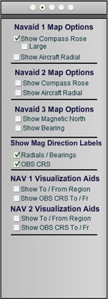
NAV 2 Visualization Aids
Show To/from: selects whether the to and from area of the navaid tuned to NAV 2 will be shaded and displayed on the map.
Holding Pattern Template Non Standard (left turns): if enabled, the holding template will be shown for left turn holding patterns. If disabled, the standard right holding pattern turns will be depicted. View: Sector Division Lines: draws the line at the division of each sector. Inbound CRS: draws a line and arrow in the direction of the inbound course. Course Abeam Lines: draws two lines abeam the inbound course. Holding Symbol: shows a race track pattern symbol that depicts the direction of turns for the holding pattern. Note that this symbol is not drawn to scale and should only be used to determine the direction of turns for the holding pattern. Auxiliary / Reference Marks Relative to: selects if the reference line template will be relative to a particular navaid or intersection. Ref Line Course: selects the direction that the reference line will be drawn. “Recip” button changes that value in 180°. Ref on Outbound Course: selects if the line will be drawn from, or outbound of, the reference point. Ref on Inbound Course: selects if the line will be drawn to, or inbound of, the reference point. |
|
||||
Ref on Both: selects whether the line will be drawn both inbound and outbound of the reference point.
Show Ref Line Labels: if selected displays labels for the direction in degrees of the course of the reference line.
Show Angle Relative to Acft:
Relative to Heading: draws a line from the aircraft in the direction of its heading. If that line intersects the reference line an angle symbol and a label displaying the relative angle in degrees between the two lines will be displayed.
Relative to Acft Track: draws a line from the aircraft in the direction of its track. If that line intersects the reference line an angle symbol and a label displaying the relative angle in degrees between the two lines will be displayed.
Relative to Rad: draws a line from the Navaid to the aircraft and displays an angle between that line and the reference line. Additionally a label showing the value for the radial in degrees relative to the aircraft position is drawn. Relative to Brg: draws a line from the aircraft to the Navaid and display the angle between that line and the reference line. Additionally a label with the bearing from the aircraft to the navaid in degrees is drawn. Show Angle Forward of Point: determines if the angle displayed between the reference line and the second line is drawn before or after the point that they intersect
Keyboard Commands and Shortcuts
Disclaimer and copyright information. |
|
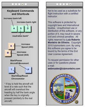
Disclaimer
CAUTION: The behavior of the instruments and other information displayed is approximate for illustration purposes only and may not reflect the actual readings on real aircraft.
All rights reserved to luizmonteiro.com.