| Bank Angle and the Physics of Standard Rate Turns |
By: Luiz Roberto Monteiro de Oliveira |
© 2010 |
Table of Contents
In this article we are going to look deep into standard rate turns and examine the math and some of physics behind them. We are also going to look at the "rule of thumb" (mental calculation) methods that pilots use to estimate the bank angle required to achieve a standard rate turn. We will verify how precise are they in comparison to an exact formula that we will construct.
Defining Standard Rate Turn
Definition: A standard rate turn is maneuver in which an aircraft turns at a rate 3o per second (3o/s) .
If this turn is held for exactly two minutes (120 seconds) the aircraft will complete a 360o turn since:
3o/s · 120s = 360o
| Note: | the middle dot (·) in the formula below means multiply. We will be using this notation throughout this text. |
The bank required to achieve standard rate changes with your true airspeed (TAS). The higher that speed, the greater the bank angle will need to be in order to achieve a standard rate turn.
 |
 |
||
| (a) | (b) |
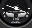
Fig 1-1 Instruments used to measure rate of turn in aircraft.
Figure 1-1 a shows an analog turn coordinator instrument that currently indicates a standard rate turn to the right (tip of the miniature aircraft wing on right marking). Figure 1-1 b shows the same situation on a digital display (magenta arc on second right marking). Note that these instruments are showing how fast the heading of the aircraft is changing (rate of turn). They do not show bank directly.
Estimating the Bank Angle to Achieve a Standard Rate Turn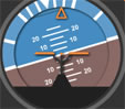 |
 |
||
| (a) | (b) |
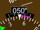
Fig 1-2 Attitude indicator instruments used to bank the aircraft.
When banking the aircraft to execute a standard rate turn, it is useful for pilots to have an approximate idea of how much that bank should be for standard rate. They will be using the attitude indicator (Figure 1-2 a & b) first to bank the aircraft and once they are at the approximate bank, they will then rely on the turn coordinator instrument (Figure 1-1 a & b) to adjust the initial bank so that a standard rate turn is established.
The following was taken directly from a paragraph in the FAA-H-8083-15A Instrument Flying Handbook, Page 5-19 and 5-20, 2008 Edition, published by United States Department of transportation, Federal Aviation Administration Air Men Testing Standards Branch:
"A rule of thumb to determine the approximate angle of bank required for a standard rate turn is to use 15 percent of the true airspeed. A simple way to determine this amount is to divide the airspeed by 10 and add one-half the result. For example, at 100 knots, approximately 15o of bank is required (100 ÷ 10 = 10 + 5 = 15); at 120 knots, approximately 18o of bank is needed for a standard rate turn."
in other words:

![]() 0.15 · TAS
0.15 · TAS
Where: is the bank angle in degrees and TAS is the true airspeed in knots. This equation will later be referred to as equation ![]() .
.
| Note: | the ( |
There are also some variations to this approximation method. One of them is:
![]() 0.10 · TAS + 5
0.10 · TAS + 5
Basically meaning: take 10% of the true airspeed then add five to get the approximate bank angle in degrees for standard rate turn. This equation will later be referred to as equation ![]()
II - Forces Acting on Aircraft (constant altitude)
We're going to begin by looking at the physics and geometry of a standard rate turn starting with the straight and level flight before the turn.
Straight and Level Flight Before the Turn
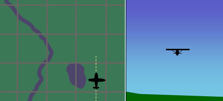
Fig 2-1 Aircraft flying straight and level
Figure 2-1 shows our hypothetical aircraft flying straight and level. The left image is the top map view, and the image on the right represents the aircraft as seen from behind.
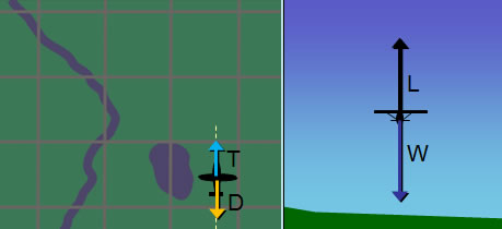
Fig 2-2 Aircraft flying straight and level (thrust, drag, lift and weight forces)
Figure 2-2 on the left shows the thrust (T) and drag (D) forces. Since the aircraft's true air speed (TAS) will remain constant during straight and level flight and then subsequently during the execution of the standard rate turn in our hypothetical example, we are not going to concern ourselves with these forces. Also note that thrust (T) and drag (D) will cancel each other out both before and during the turn, but they will not remain the same. During the turn, drag (D) will increase due to the need to generate more lift; as a result more thrust (T), added by the pilot, will be necessary to compensate for this increase in drag. This thrust increase is necessary if airspeed is to remain constant. We will examine why lift has to increase in more detail shortly.
Figure 2-2 on the right shows the lift (L) and the opposing weight (W) force during straight and level flight. During this flight condition these forces cancel each other out. That is why the aircraft will remain at its altitude and flight path (provided it is not already climbing or descending) and will not accelerate vertically (begin to ascend or descend).
During Standard Rate Turn
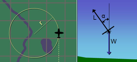
Fig 2-3 Aircraft banking (lift and weight forces)
Figure 2-3 on the right shows the lift (L) and weight (W) forces when the aircraft banks at an angle and begins the circular turn. Although not obvious in figure 2-3, as the aircraft's bank angle increases, the lift (L) force has to increase if the aircraft is to remain at the same altitude. This is because the part of the lift acting vertically has to remain the same to counteract weight. As the aircraft banks and lift force is tilted, less of it is acting vertically so the only way to compensate for that is to increase lift (L).
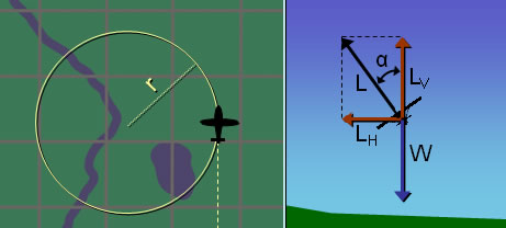
Fig 2-4 Aircraft banking (lift components and weight forces)
In figure 2-4, the lift force (L), which we can refer to as total lift, is shown broken down to its horizontal (LH) and vertical (LV) components. These are not additional forces, they are simply another way to represent the total lift force (L) . The total lift force (L) can also be thought as a resultant force of those horizontal (LH) and vertical (LV) lift forces.
Now we can see more clearly how the vertical lift (LV) counteracts the weight (W). When the aircraft banked, the lift force increased such that it's vertical component (LV) remained equal and opposite to the weight (W) force. Otherwise the aircraft's altitude would change. Therefore the vertical component of lift (LV) and weight force (W) will cancel each other out during the bank, leaving the horizontal component of lift (LH) as the remaining force. This horizontal component of lift (LH) force is what will make the aircraft turn in a circular flight path.
IMPORTANT: We are assuming the turn is coordinated (ball centered). There should be no slip or skid.
III - Obtaining an Exact Equation for the Bank Angle Required
for a Standard Rate Turn
Our goal, now that we understand the forces involved in the turn, is to obtain an exact equation. The input will be the aircraft's true airspeed (TAS) and output will be the bank angle for standard rate turn. The technique to handle these types of problems, is to try to come up with equations that describe the geometry and physics. These equations are then combined in a way as to solve for the variables that were interested in.
Fig 3-1 Lift force, its components and relationship with the bank angle
Let's begin by examining how lift relates to the bank angle during our turn (see Fig 3-1).
 |
 |
Fig 3-2 The lift force and its components form a right triangle.
In figure 3-2, the side opposite to is equal to LH. Now we have a right triangle whose sides are L, LH and LV; with the angle between the sides with L and LV of .
 |
Fig 3-3 Trigonometric solution to the right triangle
Rotate that triangle 90o clockwise and you can see that can be defined as the arctangent of LH over LV. This equation was derived from trigonometry and is our first equation. Note that this atan (arctangent) function is in radians not degrees.
As mentioned previously, the horizontal component of lift (LH) is the only force that does not cancel out with the others during the turn and is what makes the aircraft fly in a circle. From physics (laws of motion: centripetal force) we know that the force that causes an object to move in a circle is the centripetal force. It can be described by the following equation:
where CF is the centripetal force on the object, m is its mass, v is the speed of the object, and r is the radius of the circular path that the object is moving on. Since this force has to be equal to LH, we have:
Substituting LH for CF in equation ![]() we have:
we have:
We also know that the vertical component of lift (LV) equals the weight of the aircraft (W):
W can be defined by another equation from physics:
where W is the aircraft's weight, g is the acceleration of gravity, and m is its mass. We can substitute ![]() in
in ![]() to get:
to get:
Now we can substitute ![]() and
and ![]() in
in ![]() and get:
and get:
We are almost there. The mass "m" cancels out. The quantity v is the aircraft's speed, and we know that; "g" can be obtained easily from publications; however, "r" is not known.
We know that we are turning at a constant bank, speed and altitude. Turning also happens at a certain constant rate (3o per second for standard rate). This basically means that the heading will be changing at this rate, which we will call ![]() (lowercase Greek omega).
(lowercase Greek omega).
Fig 3-4 Aircraft flying in a circle - change in heading
We will also call ![]() (lowercase Greek theta) the angle formed by the aircraft's position, the center of the circle and a fixed horizontal line passing through the center of the circle. From figure 3-4 note that a change in heading will correspond to the same change in
(lowercase Greek theta) the angle formed by the aircraft's position, the center of the circle and a fixed horizontal line passing through the center of the circle. From figure 3-4 note that a change in heading will correspond to the same change in ![]() .
.
Fig 3-5 Aircraft flying in a circle - angular speed and aircraft speed
The rate or speed that ![]() is changing is called angular speed. This is basically the rate of turn which we called
is changing is called angular speed. This is basically the rate of turn which we called ![]() . Not to be confused with the "v" in figure 3-5, which is the aircraft's speed. "v" can also be called tangential speed in this case since the aircraft is flying a circular path. S is the length of the circular path that the aircraft has already flown, however we will not need to use it in our formulas.
. Not to be confused with the "v" in figure 3-5, which is the aircraft's speed. "v" can also be called tangential speed in this case since the aircraft is flying a circular path. S is the length of the circular path that the aircraft has already flown, however we will not need to use it in our formulas.
From physics (kinematics: angular speed) the radius "r" is a function of "v" and ![]() :
:
Great! We know ![]() and "v" so we can calculate the "r" that we needed in equation
and "v" so we can calculate the "r" that we needed in equation ![]() .
.
Now we can substitute ![]() in
in ![]() and get:
and get:
This is the equation we wanted. However, it is not exactly ready for use by pilots yet. The units in the equations above must be consistent. To do that we have to pick a system of units. If the units we need are in a different system than the one we pick, then we must convert each different unit individually. Let's pick the International Standard of Units (SI) as our standard (see table 3-1 below).
| Variables Used in Equation International Standard System of Units - SI Units |
||||||||||||||||||||
|
||||||||||||||||||||
Adapting the equation for units used in aviation
We will keep acceleration of gravity (g) in m/s2 since it is the most common unit for g. For the remaining units the table below gives each unit and the number that it has to be multiplied by for it to be converted to SI units and used in equation ![]() .
.
| Variables Used in Equation Used in Aviation (Speed in Knots) |
|||||||||||||||||||||||||||
|
|||||||||||||||||||||||||||
Applying all the conversion multipliers in equation ![]() we get:
we get:
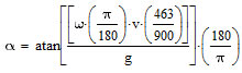 |
Now let's use some more user-friendly names for the symbols:
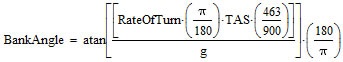 |
Equation ![]() b is exact, however, at some point we will have to reduce this equation to something more usable. Substituting: the Rate of Turn = 3o/s for standard rate; using the conventional standard for g, which is 9.80665 m/s2; and evaluating up to 5 significant digits we get:
b is exact, however, at some point we will have to reduce this equation to something more usable. Substituting: the Rate of Turn = 3o/s for standard rate; using the conventional standard for g, which is 9.80665 m/s2; and evaluating up to 5 significant digits we get:
Bank Angle = 57.296 · atan (0.0027467 · TAS) ![]() c
c
Equation ![]() c gives the exact (with up to 5 significant digits of precision) bank angle in degrees for a standard rate turn. TAS is the true airspeed in knots.
c gives the exact (with up to 5 significant digits of precision) bank angle in degrees for a standard rate turn. TAS is the true airspeed in knots.
IV - Obtaining Approximate Equations for Mentally Estimating the
Bank Angle Required for Standard Rate Turn
Arctangent Approximation
Under certain conditions:
![]()
is a very good approximation of:
![]()
Note that the atan (arctangent) function must be in radians.
| Comparing Numerical Values for Arctangent (in Radians) with the Approximation |
||||||||||||||||||||||||||||||||||||||||||||||||||||||||
|
||||||||||||||||||||||||||||||||||||||||||||||||||||||||
Table 4-1 above shows several values for x and the corresponding y results. Decimals were placed to indicate the precision that the calculations were made. Notice that for values under 0.268 the difference is 2% or less.
Arctangent (in Radians) Approximation and Error 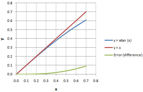 |
In chart 4-1 you can visualize how the y = atan (x) function is very close to the straight line given by y = x for values closer to zero.
It is hard to see what this means for us when we are working in radians. The arctangent (atan) function in radians can be converted to degrees by simply multiplying it by a conversion constant c1.
Therefore we have:
| where: |
and the simplified function will be:
| where: |
| Comparing Numerical Values for Arctangent (in Degrees) with the Approximation |
||||||||||||||||||||||||||||||||||||||||||||||||||||||||
|
||||||||||||||||||||||||||||||||||||||||||||||||||||||||
Table 4-2 shows the values of y in degrees. For example when the value of the arctangent in degrees is 20, the simplified function will have a value of 20.9. This difference of 0.9 is approximately a 4% error. The higher the amount of degrees, the higher the error. For 35o the error is 15%. However for smaller angles the error is practically negligible.
Arctangent (in Degrees) Approximation and Error 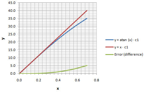 |
Chart 4-2 helps visualize how the error is very minute for small angles and gets progressively larger once you pass about 25o.
Applying the Arctangent Approximation to our Formula for Bank Angle
Bank Angle = 57.296 · atan (0.0027467 · TAS) ![]() c
c
Applying our simplification for arctangent, equation ![]() c becomes:
c becomes:
Bank Angle ![]() 57.296 · 0.0027467 · TAS
57.296 · 0.0027467 · TAS
Once again "![]() " is just a reminder that this is an approximation. Now if we multiply the two numbers in our equation we will have:
" is just a reminder that this is an approximation. Now if we multiply the two numbers in our equation we will have:
Bank Angle ![]() 0.15737 · TAS
0.15737 · TAS ![]()
Notice how remarkably close equation ![]() is to the rule of thumb formula discussed in the beginning of this article:
is to the rule of thumb formula discussed in the beginning of this article:
![]() 0.15 · TAS
0.15 · TAS
or:
Bank Angle ![]() 0.15 · TAS
0.15 · TAS
We had to go a long ways, but now we know where the rule of thumb formula comes from and what modifications had to be made to the exact formula in order to obtain it. Remember that Bank Angle in these two formulas is in degrees and TAS is in knots.
In summary we have the following (see table 4-3 below) equations for obtaining the bank angle for standard rate turn as a function of true airspeed (TAS):
| Bank Angle Equations for Standard Rate Turn | |||||||||||||||||||||||
|
|||||||||||||||||||||||
The two rule of thumb equations that we discussed in the beginning of the article were numbered ![]() and
and ![]() so that we can refer to them later in the text. These are the equations that are easily mentally calculated because of their simplicity. In the next section we'll examine how precise they are.
so that we can refer to them later in the text. These are the equations that are easily mentally calculated because of their simplicity. In the next section we'll examine how precise they are.
At Low Speeds:
Standard Rate Turn Bank Angle (Low Speeds) 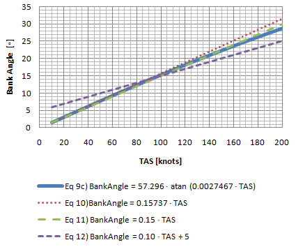 |
Chart 5-1 graphs each equation. The solid blue line is the exact equation ![]() c. At a quick glance it seems that equation
c. At a quick glance it seems that equation ![]() remains consistently close to the exact equation throughout the true airspeed (TAS) range. This happens to be the rule of thumb equation outlined in the FAA handbook (see section I).
remains consistently close to the exact equation throughout the true airspeed (TAS) range. This happens to be the rule of thumb equation outlined in the FAA handbook (see section I).
Standard Rate Turn Bank Angle Error (Low Speeds)  |
In chart 5-2 we can take a closer look at the deviations (errors) from the exact equation . Of the two equations that can be mentally calculated, once again equation ![]() is the one with the least amount of error overall throughout the true airspeed range. Equation
is the one with the least amount of error overall throughout the true airspeed range. Equation ![]() is more precise than equation
is more precise than equation ![]() up to approximately 100 knots, but then the error increases abruptly after that. Equation
up to approximately 100 knots, but then the error increases abruptly after that. Equation ![]() is only more precise than the others throughout a very narrow range from about 83 to 100 knots.
is only more precise than the others throughout a very narrow range from about 83 to 100 knots.
At High Speeds:
Standard Rate Turn Bank Angle (High Speeds)  |
From chart 5-3 it seems equation ![]() is better over a wider range than the others. It is also evident that equation
is better over a wider range than the others. It is also evident that equation ![]() begins to deviate greatly from the exact equation at close to 600 knots.
begins to deviate greatly from the exact equation at close to 600 knots.
Standard Rate Turn Bank Angle Error (High Speeds)  |
Chart 5-4 gives a clearer look at how much each equation is deviating from the exact equation. Even though equation ![]() is better over a wider range, equation
is better over a wider range, equation ![]() works better than equation
works better than equation ![]() up to about 300 knots. Equation
up to about 300 knots. Equation ![]() has an error of less than 5o from 300 knots up until about 580 knots.
has an error of less than 5o from 300 knots up until about 580 knots.
Conclusion:
Its is probably best to use equation ![]() up to 300 knots. From 300 knots to 580 knots equation
up to 300 knots. From 300 knots to 580 knots equation ![]() is better overall in that range. Above 580 knots it's probably best not to use any of the approximate equations. Beyond around 600 knots the bank angle is going to start to exceed 60o and it will be highly unlikely that any civilian aircraft is going to want to exceed that bank angle while flying instruments.
is better overall in that range. Above 580 knots it's probably best not to use any of the approximate equations. Beyond around 600 knots the bank angle is going to start to exceed 60o and it will be highly unlikely that any civilian aircraft is going to want to exceed that bank angle while flying instruments.
Most pilots in heavier commercial aircraft normally don't exceed banks beyond 30o. However notice how in chart 5-3, in the previous section, that at slightly above 200 knots, the bank angle for standard rate will exceed 30o. To address this issue pilots will many times do a ½ standard rate turn. In other words instead of taking 2 minutes to complete a 360o turn, it will take 4 minutes.
For a ½ standard rate turn, since:
4 minutes = 4 · 60 seconds = 240 seconds
the aircraft will have to turn at a rate of:
360o / 240= 1.5o per second
Now we will go back to equation ![]() b and plug-in 1.5o/s instead of 3o/s for the Rate of Turn:
b and plug-in 1.5o/s instead of 3o/s for the Rate of Turn:
|
Substituting: the Rate of Turn = 1.5o/s for standard rate; using the conventional standard value for g, which is 9.80665 m/s2; and evaluating up to 5 significant digits we get:
Bank Angle = 57.296 · atan (0.0013734 · TAS) ![]() d (for ½ standard rate)
d (for ½ standard rate)
which we will call equation ![]() d. Applying our simplification of arctangent, equation
d. Applying our simplification of arctangent, equation ![]() d becomes:
d becomes:
Bank Angle ![]() 57.296 ·0.0013734· TAS (for ½ standard rate)
57.296 ·0.0013734· TAS (for ½ standard rate)
Now if we multiply the two numbers in our equation we will have:
Bank Angle ![]() 0.078685 · TAS
0.078685 · TAS ![]() (for ½ standard rate)
(for ½ standard rate)
The equation above is for a ½ standard rate turn. It is basically the same as taking the approximate equation ![]() (below), from section IV, for the standard rate turn and dividing it by two (0.15737 / 2 = 0.078685).
(below), from section IV, for the standard rate turn and dividing it by two (0.15737 / 2 = 0.078685).
Bank Angle ![]() 0.15737 · TAS
0.15737 · TAS ![]() (for standard rate)
(for standard rate)
Let's go ahead then and take the other equations that we used for standard rate turn ( ![]() and
and ![]() ) divide them by two and see how close we get to the bank bangle for ½ a standard rate turn given by the exact equation
) divide them by two and see how close we get to the bank bangle for ½ a standard rate turn given by the exact equation ![]() d.
d.
| Bank Angle Equations for ½ Standard Rate Turn | |||||||||||||||||||||||
|
|||||||||||||||||||||||
The rule of thumb equations ![]() and
and ![]() that we used for standard rate turn are now divided by two and called
that we used for standard rate turn are now divided by two and called ![]() and
and ![]() respectively.
respectively.
Comparing the Approximations for ½ Standard Rate to the Exact Formula
At Low Speeds:
½ Standard Rate Turn Bank Angle (Low Speeds)  |
Chart 6-1 graphs each equation. The solid blue line is the exact equation ![]() d. At a quick glance it seems that equation
d. At a quick glance it seems that equation ![]() and
and ![]() remain consistently close to the exact equation throughout the true airspeed (TAS) range.
remain consistently close to the exact equation throughout the true airspeed (TAS) range.
½ Standard Rate Turn Bank Angle Error (Low Speeds)  |
In chart 6-2 we can take a closer look at the deviations from the exact equation (errors). Equation ![]() is the one with the least amount of error overall throughout the true airspeed range but this equation is not easily used for mental calculation. Equation
is the one with the least amount of error overall throughout the true airspeed range but this equation is not easily used for mental calculation. Equation ![]() is more precise than equation
is more precise than equation ![]() but the difference is less than half a degree. Equation
but the difference is less than half a degree. Equation ![]() is only more precise than the others throughout a very narrow range from about 80 to 100 knots.
is only more precise than the others throughout a very narrow range from about 80 to 100 knots.
At High Speeds:
½ Standard Rate Turn Bank Angle (High Speeds)  |
From chart 6-3 it looks like the bank angle exceeds 30o at around 420 knots. The chart below will give a better picture of the errors.
½ Standard Rate Turn Bank Angle Error (High Speeds)  |
Chart 6-4 equation ![]() is better up to about 640 knots, however all equations are off by at least 7o at that point. Equation
is better up to about 640 knots, however all equations are off by at least 7o at that point. Equation ![]() has an error of less than 5o up to about 580 knots and less than 2o at or below 400 knots.
has an error of less than 5o up to about 580 knots and less than 2o at or below 400 knots.
Conclusion:
If you used equation ![]() for estimating the bank angle for a regular standard rate turn, you can divide it by two (which yields equation
for estimating the bank angle for a regular standard rate turn, you can divide it by two (which yields equation ![]() ) and get a pretty good estimate of the bank angle for ½ standard rate turn for speeds up to 400 knots (less than 2o error).
) and get a pretty good estimate of the bank angle for ½ standard rate turn for speeds up to 400 knots (less than 2o error).
What about if TAS is in kilometers per hour (km/hr)? It is probably not necessary to go in detail over the whole process again, but here are the equations:
As before, we will keep acceleration of gravity (g) in m/s2 since it is the most common unit for g. For the remaining units the following table gives each unit and the number that it has to be multiplied by for it to be converted to SI units and used in equation ![]() .
.
| Variables Used in Equation Used in Aviation (Speed in km/hr) |
|||||||||||||||||||||||||||
|
|||||||||||||||||||||||||||
Applying all the conversion multipliers in equation ![]() we get:
we get:
 |
More user-friendly names for the symbols yields:
 |
Reducing this equation to something more usable. Substituting: the Rate of Turn = 3o/s for standard rate; use the conventional standard for g, which is 9.80665 m/s2; and evaluating up to 5 significant digits we get:
Bank Angle = 57.296 · atan (0.0014831 · TAS) ![]() e
e
Equation ![]() e gives the exact (with up to 5 significant digits of precision) bank angle in degrees for a standard rate turn. TAS is the true airspeed in km/h.
e gives the exact (with up to 5 significant digits of precision) bank angle in degrees for a standard rate turn. TAS is the true airspeed in km/h.
Applying our simplification of arctangent, equation ![]() e becomes:
e becomes:
Bank Angle ![]() 57.296 · 0.0014831 · TAS
57.296 · 0.0014831 · TAS
Now if we multiply the two numbers in our equation we will have:
Bank Angle ![]() 0.084976 · TAS
0.084976 · TAS ![]()
Equation ![]() does not yield a nice rule of thumb formula with km/hr as it did with knots. Lets try some different formulas and try to figure out an easy way, if there is one, to calculate this estimate formula.
does not yield a nice rule of thumb formula with km/hr as it did with knots. Lets try some different formulas and try to figure out an easy way, if there is one, to calculate this estimate formula.
We'll try the following equations that are easy to calculate and are somewhat close to equation ![]() :
:
![]() 0.09 · TAS
0.09 · TAS ![]()
![]() 0.1 · TAS
0.1 · TAS ![]()
![]() 0.1 · TAS -2
0.1 · TAS -2 ![]()
![]() 0.1 · TAS -10
0.1 · TAS -10 ![]()
Comparing the Approximations for Standard Rate to the Exact Formula (in km/hr)
At Low Speeds:
Standard Rate Turn Bank Angle (Low Speeds) (TAS in km/hr) 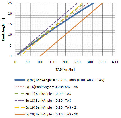 |
Chart 7-1 graphs each equation. The solid blue line is the exact equation ![]() e. At a quick glance it seems that the only equations that are easy to calculate and remain close to the exact equation throughout this true airspeed (TAS) range are equations
e. At a quick glance it seems that the only equations that are easy to calculate and remain close to the exact equation throughout this true airspeed (TAS) range are equations ![]() and
and ![]() .
.
Standard Rate Turn Bank Angle Error (Low Speeds) (TAS in km/hr)  |
In chart 7-2 we can take a closer look at the deviations (errors) from the exact equation. Apart from the exact equation ![]() e, equation
e, equation ![]() is the one with the least amount of error overall throughout the true airspeed range, but it is not easy to calculate mentally. Equation
is the one with the least amount of error overall throughout the true airspeed range, but it is not easy to calculate mentally. Equation ![]() is more precise than equation
is more precise than equation ![]() by almost two degrees. Ignoring equations
by almost two degrees. Ignoring equations ![]() and
and ![]() e, equation
e, equation ![]() is more precise than the others throughout a range from about 100 to 200 km/hr; then equation
is more precise than the others throughout a range from about 100 to 200 km/hr; then equation ![]() becomes more precise until about 320 km/hr; after that equation
becomes more precise until about 320 km/hr; after that equation ![]() is more precise but has an error of more than 5o after around 540 km/hr (see chart 7-4 below).
is more precise but has an error of more than 5o after around 540 km/hr (see chart 7-4 below).
At High Speeds:
Standard Rate Turn Bank Angle (High Speeds) (TAS in km/hr) 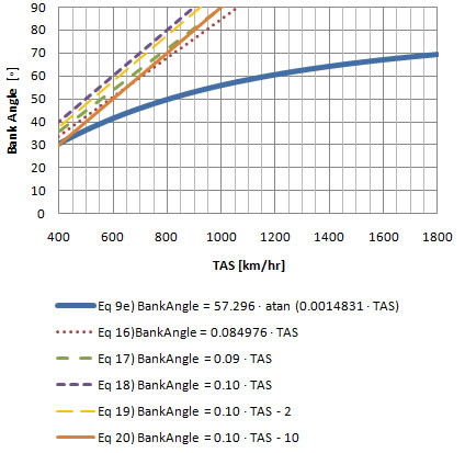 |
From chart 7-3 It looks like the bank angle passes 30o at around 400 km/hr. The chart below will give a better picture of the errors.
Standard Rate Turn Bank Angle Error (High Speeds) (TAS in km/hr) 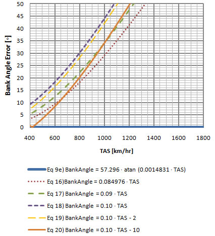 |
As mentioned previously, equation ![]() is more precise from 320 km/hr but has an error of more than 5o after around 540 km/hr.
is more precise from 320 km/hr but has an error of more than 5o after around 540 km/hr.
Conclusion:
The best equation will really depend on your speed range:
- From 10 - 100 km/hr equation
 with a maximum error of 0.5o.
 - From 100 - 200 km/hr equation
 with a maximum error of 1.5o.
 - From 200 - 320 km/hr equation with a maximum error of 3.5o.
- From 320 - 540 km/hr equation
 with a maximum error of 5o.
To make things even simpler, if you don't mind a little more error from 100 - 200 knots, you can use:
- From 10 - 320 km/hr equation with a maximum error of 3.5o.
- From 320 - 520 km/hr equation with a maximum error of 5o.
VIII - Units and Variables Used
| International System of Units (SI Units) | |||||||||||||||||||||||||||||||||||||||||
|
|||||||||||||||||||||||||||||||||||||||||
| Variables and Constants Used | |||||||||||||||||||||||||||||||||||||||||||||||||||||||||||
|
|||||||||||||||||||||||||||||||||||||||||||||||||||||||||||
| Variables Used in Equations and their SI Conversion Multipliers | |||||||||||||||||||||||||||||||||||||||||||||||||||||||||||||||||||||||||||||||||||||||
|
|||||||||||||||||||||||||||||||||||||||||||||||||||||||||||||||||||||||||||||||||||||||
IX - Other Useful Information that We Can Use From Our Study
As we constructed our mathematical model for standard rate turns we came across many formulas that are useful. In this section lets quickly highlight a few.
A - Radius of Turn Formula (as a function of speed and rate of turn)
where r is the radius of turn, v is the speed of the aircraft and ![]() is the rate of turn. Variables r, v and
is the rate of turn. Variables r, v and ![]() are in SI units: m, m/s and rad/s. We will apply the conversion multipliers so that r, v,and
are in SI units: m, m/s and rad/s. We will apply the conversion multipliers so that r, v,and ![]() can be given in Nm, knots and o/s respectively. Applying the conversion multipliers on table 8-3:
can be given in Nm, knots and o/s respectively. Applying the conversion multipliers on table 8-3:
 |
Renaming r, v and ![]() to the more user friendly RadiusOfTurn, TAS (true airspeed) and RateOfTurn respectively, we have:
to the more user friendly RadiusOfTurn, TAS (true airspeed) and RateOfTurn respectively, we have:
where RadiusOfTurn, TAS and RateOfTurn are given in Nm, knots and o/s respectively.
Evaluating ![]() and fractions to five significant digits:
and fractions to five significant digits:
For a standard rate turn (RateOfTurn = 3o/s) ONLY, we have:
RadiusOfTurn = 0.00053052 · TAS
where RadiusOfTurn and TAS are given in Nm and knots respectively. This equation is exact up to five significant digits.
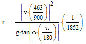
B - Radius of Turn Formula (as a function of speed and bank angle)
Equation ![]() can be rearranged and solved for "r" as follows:
can be rearranged and solved for "r" as follows:
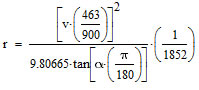
where r is the radius of turn, v is the speed of the aircraft, g is the acceleration of gravity and ![]() is the angle of bank. Variables r, v, g and
is the angle of bank. Variables r, v, g and ![]() are in SI units: m, m/s, m/s2 and rad respectively. We are going to keep "g" in SI units and use the standard value of 9.80665 m/s2 for it. We will apply the conversion multipliers so that r, v,and
are in SI units: m, m/s, m/s2 and rad respectively. We are going to keep "g" in SI units and use the standard value of 9.80665 m/s2 for it. We will apply the conversion multipliers so that r, v,and ![]() can be given in Nm, knots and o respectively. Applying the conversion multipliers on table 8-3:
can be given in Nm, knots and o respectively. Applying the conversion multipliers on table 8-3:
 |
 |
Renaming r, v and ![]() to the more user friendly RadiusOfTurn, TAS (true airspeed) and BankAngle, we have:
to the more user friendly RadiusOfTurn, TAS (true airspeed) and BankAngle, we have:
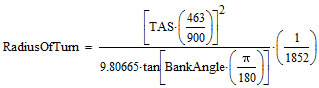 |
where RadiusOfTurn, TAS and BankAngle are given in Nm, knots and o respectively.
Evaluating ![]() and fractions to five significant digits:
and fractions to five significant digits:
C - Load Factor Formula (as a function of bank angle)
Load factor is defined as the total lift to weight ratio:
| (new equation) |
Where L is the total lift and W is the weight of the aircraft. We now need to find an equation for L:
|
From our triangle that we got from analyzing the geometry of a standard rate turn in section III we can get the following equation that will give us total lift (L):
Where ![]() , LV, and L are the bank angle, vertical lift and total lift respectively. Since vertical lift has to equal weight:
, LV, and L are the bank angle, vertical lift and total lift respectively. Since vertical lift has to equal weight:
we can substitute ![]() in
in ![]() to get:
to get:
we can substitute ![]() in
in ![]() to get:
to get:
Notice how weight (W) cancelled out. Note that ![]() is in SI unit: radians. LoadFactor has no unit. We will apply the conversion multiplier so that
is in SI unit: radians. LoadFactor has no unit. We will apply the conversion multiplier so that ![]() can be given in o. Applying the conversion multiplier on table 8-3:
can be given in o. Applying the conversion multiplier on table 8-3:
 |
Renaming ![]() to the more user friendly BankAngle, we have:
to the more user friendly BankAngle, we have:
 |
Evaluating ![]() and fractions to five significant digits:
and fractions to five significant digits:
where BankAngle is given in o. The charts below graph this formula.
Load Factor vs Bank Angle (at bank angles up to 80o)  |
Chart 9-1 graphs the load factor at bank angle up to 80o. At 80o the load factor is almost 6. This would mean that a pilot performing a level turn at this bank angle would experience almost 6 times the force of gravity (or 6g's).
Load Factor vs Bank Angle (at bank angles from 80o to 89o) 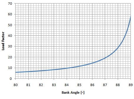 |
Chart 9-2 graphs the load factor at bank angles from 80o to 89o. Notice how abruptly the load factor increases. As the bank angle approaches 90o, the load factor approaches infinity (not possible to show in the graph).
All rights reserved to Luiz Roberto Monteiro de Oliveira.